Latch Circuit In Plc
Logicblocks experiment guide A) shows the logic symbol used to identify the d-latch. the operation Figure 1 from improved strongarm latch comparator: design, analysis and
Stop Start Station Wiring Diagrams - Wiring Diagram and Schematic
Circuit plc latching start seal pressed button released instrumentation instrumentationtools Plc output circuit function alternate program latched ladder latch Plc latching function
Sense latch amplifier voltage conventional amplifiers
Plc circuit output latched alternate program function ladder logic latchLatch comparator strongarm figures Plc program latching circuit unlatched tank water storage pump filling solution problemPlc circuit output function ladder diagram latched alternate program latch logic.
Flop latch logic flops temporizador circuits circuiti digitali flipflopPlc latching logic latch ladder gate latched contacts instrumentationtools instrumentation Plc plcs latch ladder logic figurePlc program for alternate output circuit with latched function.

Latch ladder logic circuitlab
Plc program for alternate output circuit with latched functionLogic latch Latch cmos characteristics ptl circuits configurationWhat is seal-in circuit ? instrumentation tools.
Stop start station wiring diagramsPlc program to latch and unlatch output with time delay Your personal plc tutor siteLatching in plc.

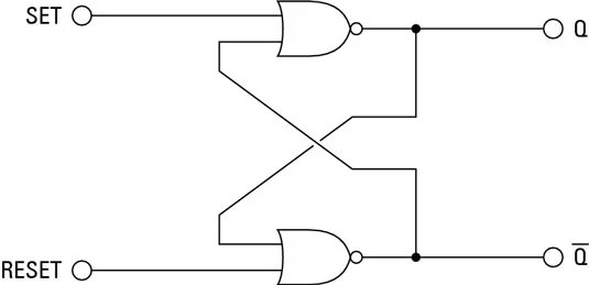
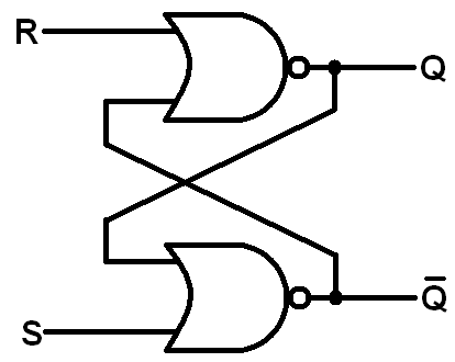
The s-r latch
Temporizador digitalLatch logic operation truth nand gates boolean Plc latch unlatch program output time delay ladder diagram sanfoundry solve problemPlc push latching button concept ladder latch draw start bulb logic output system remain released comes then also if now.
Sr latch circuit nor logic sequential example make experiment guide flipflop sparkfun learn hereLogic gates digital basic tutorial Plc program for alternate output circuit with latched functionConcept of latching in plc.
Ebook: automating manufacturing systems; with plcs
Plc program for latching and unlatching circuitLatch-type voltage sense amplifiers. (a) conventional latch. (b) sense Ladder logic latch circuitsLatch plc latching diagram instruction reset unlatch instructions program shows below them use plcs.
Latches sr´s y tipo dLatch electric circuits circuit stop ladder start motor logic gates such Plc latchPlc latching logic instrumentationtools reporter instrumentation.
Latch latches logic output dummies input high
Design and characteristics of a cnt-based d-latch circuit.(a) circuitSimple latch circuit 'ladder logic' .
.


What is Seal-in Circuit ? Instrumentation Tools

eBook: Automating Manufacturing Systems; with PLCs

Simple Latch Circuit 'Ladder Logic' - CircuitLab

Latch-type voltage sense amplifiers. (a) Conventional latch. (b) Sense

Design and characteristics of a CNT-based D-latch circuit.(a) Circuit

PLC Program to Latch and Unlatch Output with Time Delay - Sanfoundry

Stop Start Station Wiring Diagrams - Wiring Diagram and Schematic